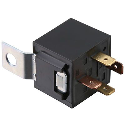
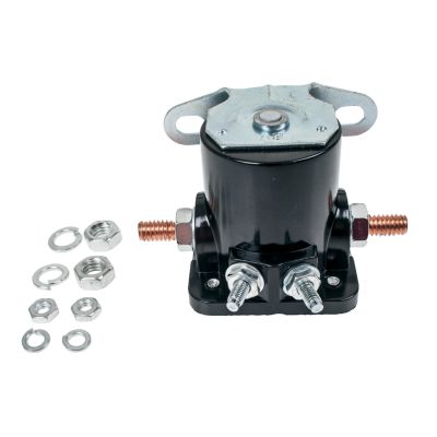
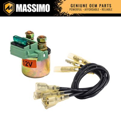
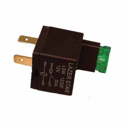
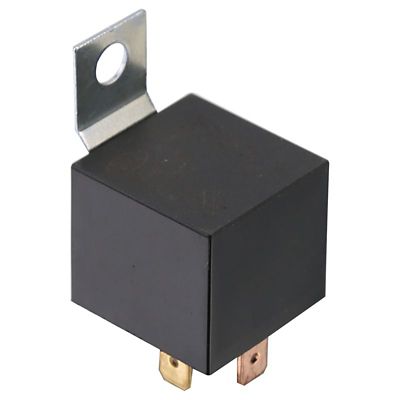
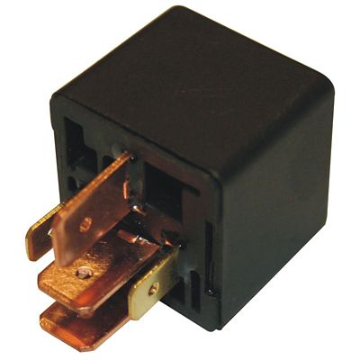
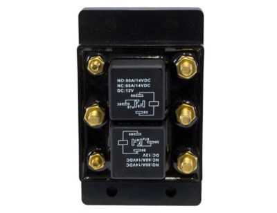
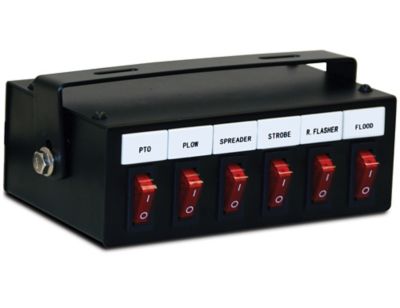
An electrical relay is an electrically operated switch that lets a low-power control signal open or close a separate circuit, often one carrying more power than the control circuit. In an electromechanical relay, electricity energizes a coil, creating a magnetic field that moves an armature and changes the position of electrical contacts. That arrangement allows a small switch, sensor, timer, or controller to operate another circuit without carrying that circuit’s full load. Around a farm, acreage, or workshop, relays can serve in pump controls, equipment lighting, ventilation controls, and other electrical systems where one device needs to tell another when to turn on or off. A dash-mounted switch, for example, may send a control signal to a relay while the relay contacts handle a properly matched lighting load. In a pump control panel, a relay may instead signal a contactor that handles the motor’s power circuit. Those are different jobs, and the distinction matters when choosing a replacement. Relays, contactors, and motor overload protection are not automatically interchangeable, even when they work together in the same enclosure. Contact arrangement also shapes what a relay does. Normally open contacts remain open when the coil is not energized and close when it energizes; normally closed contacts work the other way around. A changeover arrangement transfers a connection between two contact paths. These descriptions refer to the relay’s unenergized state, not necessarily the normal running condition of the equipment. Some applications call for solid-state relays, which switch electronically rather than through moving contacts. They operate differently from electromechanical designs and have their own load, leakage-current, and heat-dissipation requirements. For equipment owners, maintenance crews, and folks keeping a busy shop running, understanding those basic differences helps narrow the choices without treating every relay as the same little box with terminals. The right match depends on what supplies the control signal, what the switched circuit powers, and how the relay fits into the equipment’s existing electrical design.
Electrical relay selection starts with two separate sets of ratings: the control side and the switched-load side. A coil marked for 12-volt DC operation does not belong on a 120-volt AC control supply, and a contact rating does not describe the voltage needed to energize the coil. For
AC Relays, the specifications should make clear whether an AC rating refers to the control coil, the switched circuit, or both. Matching voltage alone is not enough. Contact current, load type, switching frequency, and starting demand all affect suitability. A resistive-load rating cannot automatically stand in for a motor rating, because a motor can draw substantially more current while starting than while running. Lamps, solenoids, and other loads can also have switching demands that differ from their steady operating current. Equipment documentation and the relay manufacturer’s ratings provide a better basis for selection than physical resemblance. A relay that looks right may have a different terminal layout, contact arrangement, or coil requirement. Pin count is only part of the picture: two relays with the same number of terminals can connect those terminals differently. Socket pattern, terminal numbering, mounting style, and overall dimensions matter, especially inside a crowded control enclosure or behind an equipment panel. Blade terminals, screw connections, socket-mounted designs, and board-mounted designs serve different installation needs. Available clearance must account for the connector or socket as well as the relay body. Multiple poles allow separate circuits to switch together, while the number of throws describes the available contact paths for each pole. Built-in features deserve attention, too. A DC relay with an internal suppression diode may require a particular coil polarity, and an indicator light or test button does not make an otherwise mismatched relay suitable. For replacement work, matching the original electrical function and following the equipment’s specified requirements helps prevent a simple-looking swap from changing how the system behaves. That matters whether the relay controls a shop fan, sends a pump-start signal, or switches an accessory circuit on working equipment.
Construction and placement help determine how well an electrical relay holds up through repeated operation. Electromechanical designs commonly combine an insulating housing, copper coil windings, and metal contacts selected for their switching task. Silver-alloy contact materials appear in many power-switching designs, but contact material by itself does not establish suitability for a particular load. Housing style matters just as much in the setting where the relay will work. An open-frame design belongs in an appropriate protected assembly, while an enclosed or sealed design offers a different level of protection. Sealed does not automatically mean suitable for washdown, submersion, or exposure outside an enclosure; the stated protection rating still governs. In a shop with grinding dust or a barn work area where feed dust settles on nearby surfaces, the surrounding enclosure can be an important part of keeping contamination away from electrical connections. Vibration, mounting security, wire support, and terminal condition also affect service life. A loose connection can create resistance and damaging heat, while an unsupported harness can put strain on terminals as equipment moves. Relay care generally centers on keeping the surrounding assembly clean, dry, properly enclosed, and in sound condition rather than opening the relay housing. Inspection and replacement belong with power disconnected, stored electrical energy addressed, and the equipment’s service procedures followed; line-voltage work is a job for a qualified electrician. Chattering, visible scorching, a damaged socket, or repeated contact failure can point to trouble elsewhere in the circuit rather than a relay problem alone. Repeatedly fitting another relay without checking the control supply and load can leave the underlying fault in place. Clear markings and accessible specifications make future maintenance easier, particularly when several similar-looking relays share one panel. For farm equipment, shop controls, and general maintenance work, the best fit is a relay whose electrical ratings, contact function, mounting arrangement, and protection needs line up with the job—not simply one that fits the opening.